There is a trend in robotics towards the use of backdrivable actuators due to multiple reasons. One of them, is the need of sharing the environment with humans. Such a robot needs flexibility to adapt the differences between real environmental condition and assumed environmental condition. The robot´s joints may need to be articulated by a human and that would require high backdrivable actuators with low friction.
There are many other applications where a backdrivable actuator is needed, for example, in teleoperation, when Position-Position control is implemented. In teleoperation, a master device is controlled by a human operator and a slave device placed in a safe area mimics the movements of the master device. Position-Position uses the difference in position between master and slave to calculate the feedback forces to the operator. The more the positional error, the greater the forces. This positional error would be much more reduced with non-backdrivable actuators, and then, more difficult to provide feedback to the operator. At the end of the day, what you want in your slave device is to behave like a human, to react to the external forces as a human would do. If having a very stiff slave, the positional error would be minimum in normal tasks and the operator would not feel anything.
In any circumstance where the estimation of the external forces is needed, a backdrivable actuator is preferred. This could also be the case of walking robots, where it is important to feel the impact between the leg and the ground and react accordingly with a determined compliance.
Backdrivability is essential for safe robotic-arm operation around people; operating in unstructured environments; for stable control of contact forces; and for exploiting Jacobian-Transpose safely to enable Cartesian control of forces, haptic objects, and direct Cartesian control of trajectories.
Backdrivability is the ability for interactive transmission of force between input axis and output axis. To get high backdrivability, we have to reduce friction of power transmission considerably. Backdrivability provide actuators with high force sensitivity and high impact resistance which adapts to quick external force mechanically.
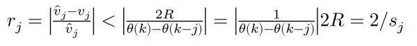
In rehabilitation robotics, particularly in upper limbrobotics, the drives must be able to deliver high torques at low velocity. Therefore, many rehabilitation robots are driven by motor-gearbox combinations. In contrast to direct-drive motors, the backdrivability of geared drives is poor due to friction in the gearbox. The back-driving torque sb can be defined as the amount of torque the human must apply to the robotic joint in order to perform a user-driven movement. Perfect backdrivability is achieved if sb = 0.
In [1] it is suggested that a reduction ratio over 60 in harmonic drives creates non-backdrivable actuators.
The backdrivability of a gearbox is highly correlated with the friction and the efficiency. Hence, let us have a look to the efficiency of different types of gears to get a initial impression of the backdrivaility of them.
In [2] a comparison between Harmonic drives and Cycloid drives is shown. In their research, Cycloid drives fitted into the same package diameter as harmonic drives with equal torque-generating capabilities. In their research, they demonstrated many advantages over harmonic drives, including substantially greater efficiency (especially at low torques) and lower reflected inertia, and often provided a thinner profile. These benefits were offset, however, by substantial disadvantages, including significant backlash and gear ratio ripple.
They conclude that, neither Cycloid nor harmonic drives are universally superior for all applications and conditions. However, Cycloid drives should be considered for applications in anthropomorphic robots and prostheses, especially those in which size, inertia, and efficiency take precedence over backlash and torque ripple.
Gear Efficiency Comparison Table
| No | Type | Normal Ratio Range | Efficiency Range |
| 1 | Spur | 1:1 to 6:1 | 94-98% |
| 2 | Straight Bevel | 3:2 to 5:1 | 93-97% |
| 3 | Spiral Bevel | 3:2 to 4:1 | 95-99% |
| 4 | Worm | 5:1 to 75:1 | 50-90% |
| 5 | Hypoid | 10:1 to 200:1 | 80-95% |
| 6 | Helical | 3:2 to 10:1 | 94-98% |
| 7 | Cycloid | 10:1 to 100:1 | 75% to 85% |
Double helical gear drives are considered to be more efficient than single helical gears.
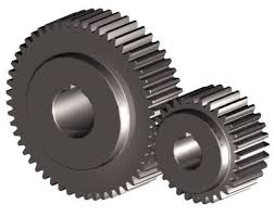
Spur Gears
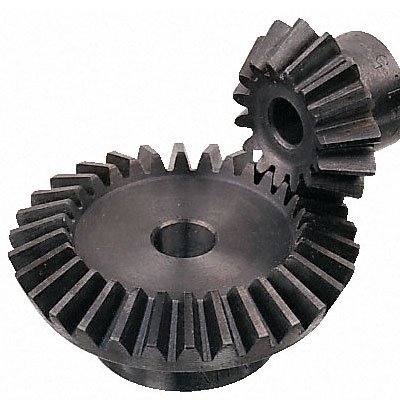
Straight Bevel Gears
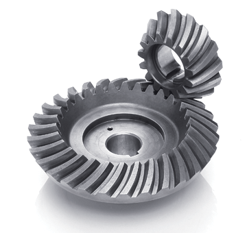
Spiral Bevel Gears
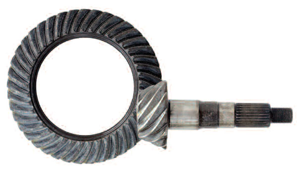
Hypoid Gears.
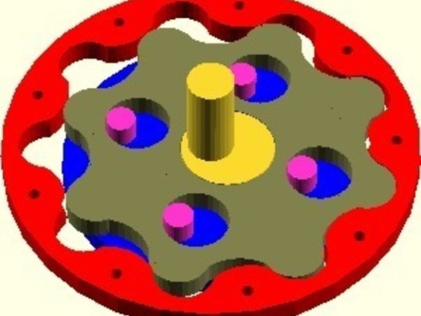
Cycloid Gear.
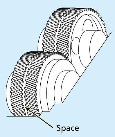
Double Helical Gears.
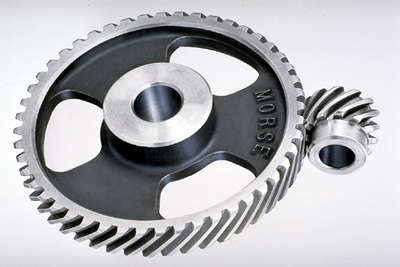
Helical Gears
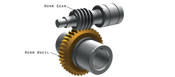
Worm Gears.
Backdrivability of ball screws
Check out my article on backdrivability of ball screws to discover the main parameters that make them backdrivable.
[1] Instrumented Harmonic Drives for Robotic Compliant Maneouvres. H. Kazerooni.
[2] Cycloid vs. Harmonic Drives for use in High Ratio, Single Stage
Robotic Transmissions. Jonathon W. Sensinger, Member, IEEE and James H. Lipsey.2012 IEEE International Conference on Robotics and Automation
RiverCentre, Saint Paul, Minnesota, USA