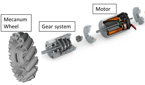
In this post I am going to review the main parameters affecting the selection of the correct motor and gears for your application.
Motors are a very common component in many devices and embedded systems. To function properly, their selection requires a careful step by step process that relies heavily on the intended operation of the motor. Therefore, before motor selection can begin, it is beneficial to define what the motor will have to do, the performance goals of the motor and overall system (i.e. how will you measure that it’s doing well), and how the motor will interact with the other system components (such as the power system). Understanding these parameters will help the selection process by keeping the focus on what your system must achieve, and in turn can help you to better define motor technical requirements.
This post and the following will use a wheeled robot in order to illustrate the process to be followed on the determination of a motor.
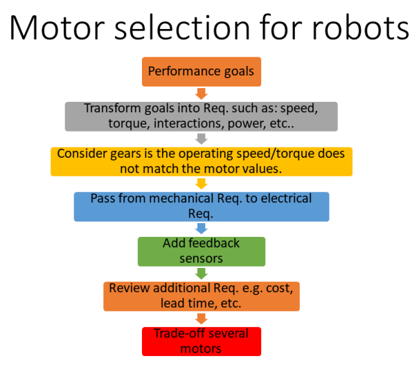
The most important steps when selecting a motor for a certain application are:
- Determine key performance goals of the system
- Transform the goals into torque and rotational speed requirements for the motor
- Speed
- Torque
- Motor connection interactions (i.e. what is the motor connected to and how does that influence its performance)
- Speed-Torque Curve
- Mechanical Power
- Constant Voltage Torque-Speed Line
- Utilize gearing systems if the operating point speed and torque do not match the motor speed and torque
- Relate these mechanical requirements into electrical power system requirements, including the potential of motor overheating
- Add sensors, such as encoders, based on the information needs of other systems
- Review additional requirements such as cost, time, environmental, serviceability and mounting requirements
- Deal with the reality that there is rarely a motor that exactly matches the calculated requirements and make proper trade-offs
- Review all requirements
- Determine rating system
- Generate a selection of motors
- Compare all options and select a motor
In the next sections, these steps will be review and explained with examples of application.
1.Determine key performance goals of the system
Let us define the standard speed of our wheeled robot. As a starting point we could have a look to the maximum speeds of common animals:
| Animal | Speed [m/h] | Speed [m/s] |
| Peregrine falcon | 200 | 35 |
| Cheetah | 70 | 12 |
| Pronghorn antelope | 61 | 11 |
| Lion | 50 | 9 |
| Cat (domestic) | 30 | 5 |
| Human | 27.89 | 5 |
| Chicken | 9 | 2 |
| House mouse | 8 | 1 |
Let us to be not very ambitious and select an easily achievable speed for the first prototype. This will be 1 m/s.
- Speed Requirement: 1 m/s
Further characteristics of the system need to be analysed to determine the required acceleration of a robot depending on the desired agility and performance.
![]() Acceleration rule of thumb: at least double than the speed for the system to be agile.
Acceleration rule of thumb: at least double than the speed for the system to be agile.
- Acceleration Requirement: 2 m/s2.
2.Transform the goals into torque and rotational speed requirements for the motor
2.1 Speed
The maximum velocity of the system (vmax) is translated into rotational speed of the wheel (nwheel) by using the wheel radius (rwheel).
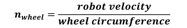
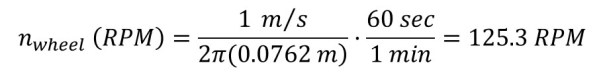
This calculated rotational speed is the desired operating wheel speed for the system. However, when selecting a motor, motors’ data sheets give ratings for a “No-Load” speed (n0) or the maximum rotational speed of the motor with nothing attached to it, i.e. having “no-load.” The motor you select will require a rated “No-Load” speed greater than your calculated operating speed because when a physical load is placed on the motor, the motor speed will naturally slow down.
2.2 Torque
To get a rough estimate of the torque (M) required, assumptions will be made that the inertia of the wheels, rolling resistance, air drag, incline, etc. are mostly negligible.
For example, for a 15 kg robot accelerating at 2 m/s2, a 30 N force is required:
If the robot is going up an incline, the force (F) will be increased by the amount required to overcome the component of gravity pulling it down the incline (see Figure).
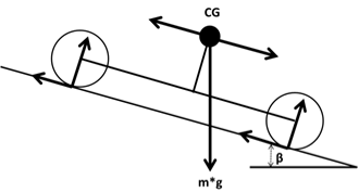
Example of vehicle dynamic forces

Assuming that the wheeled robot has 4 motors, each one moving one wheel, this force can be divided by 4 in order to get the torque that each wheel has to exert.


Based on the sample equation above, the motor chosen should have a torque provided to the wheel greater than or equal to 571 mNm. Before confirming this calculated value as the target torque, it is important to understand the maximum torque that each wheel can transmit. This is known as the traction limited torque (Mtrac). If the motor can produce more torque than the wheel can transmit, then the wheel will slip on the ground.


Based on this quick check, the desired maximum torque (M) is well below the traction limits of the wheel (Mtrac).
2.3.Speed-Torque Curve
Every motor is only able to safely produce a certain range of speed and torque outputs. These operating characteristics of a motor are often presented graphically on what is known as a torque-speed curve, shown in below.
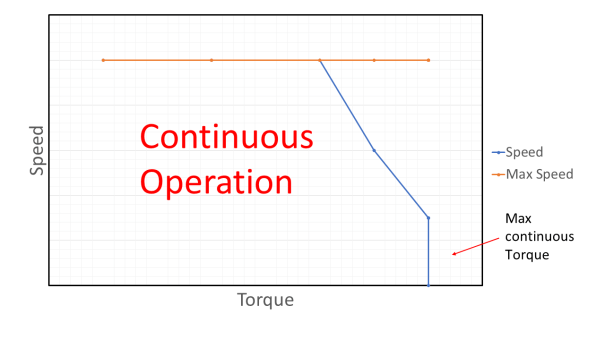
The maximum continuous torque is set mainly by the temperature limits of the internal components of the motor, assuming the motor is operating within specified environmental conditions, such as under 25°C ambient conditions, free air circulation, and no heat transfer through the flange. It is very likely the environmental conditions of your motor’s installation will be different than these. You will need to either adjust your environmental conditions, such as adding cooling fans, and/or make sure your motors will be operating well within their continuous operating range so as to not over-stress and damage or burn out the motor.
The simplest first check to see whether your requirements coincide with a motor’s continuous operating range is to also plot your most demanding torque and speed requirements on the motor’s torque curve.
In the our case, this would be the point (865 mNm, 189.86 rpm). This point should lie within the continuous operating range. Since this is the point you want your system to operate at, it is commonly referred to as your operating point. In many cases, gearing can be applied to help modify a motor’s effective continuous operating range. This is discussed more in later sections but for now, it is important to remember that you will need to select a motor size whose continuous operation region will contain your operation point whenever possible.
3. Power
The speed and torque requirements you determined earlier are also used to determine a power requirement for your motor. All motors are only able to output a maximum amount of power (Pmech, max). The power output from a motor can be utilized in mainly two (desired) ways: spinning its output shaft faster or spinning its output shaft with more torque. Hence, there is a trade-off between speed (n) and torque (M) in any motor’s operation as shown in the equations below.
![Power_{Mechanical} [W]=\frac{Torque [Nm] \cdot n [RPM]}{\frac{60}{2\cdot \Pi}}](https://s0.wp.com/latex.php?latex=Power_%7BMechanical%7D+%5BW%5D%3D%5Cfrac%7BTorque+%5BNm%5D+%5Ccdot+n+%5BRPM%5D%7D%7B%5Cfrac%7B60%7D%7B2%5Ccdot+%5CPi%7D%7D&bg=efefef&fg=555555&s=2&c=20201002)
For any given operating condition, the mechanical power can be calculated using the torque and speed of that operating point. To calculate the amount of power required for our motor selection, the speed and torque values calculated previously are entered into the power equation above to produce the equation below.
![Power_{Mechanical} [W]=\frac{ 0.865[Nm] \cdot 189.86 [RPM]}{\frac{60}{2\cdot \Pi}}=17.2 W](https://s0.wp.com/latex.php?latex=Power_%7BMechanical%7D+%5BW%5D%3D%5Cfrac%7B%C2%A00.865%5BNm%5D+%5Ccdot+189.86+%5BRPM%5D%7D%7B%5Cfrac%7B60%7D%7B2%5Ccdot+%5CPi%7D%7D%3D17.2+W&bg=efefef&fg=555555&s=2&c=20201002)
A minimum power output of 17.2 Watts is required to achieve the system level velocity and acceleration requirements. Keep in mind that there are many variables that were assumed to be negligible, and adding a safety factor is a good idea in case some variables are more significant than initially thought. These calculations narrow the range of possible motors; it’s unlikely a motor with greater than a 100 Watt output is necessary and likewise, a 15 Watt motor will not allow our robot to achieve the acceleration requirements.
4. Selecting a Motor based on your Power Rating and Operational Point
Suppliers typically list motors by their mechanical power rating, hence why it was calculated above. However, just because a motor is rated to meet your power requirements, does not mean it will work for your operating point. Remember power is a combination of the speed and the torque, so there is a continuum of speed and torque pairings that will produce the same power.
To help emphasize this point, in the figure below, a constant power curve of 17.2 Watts is plotted on the torque curve. This will help visualize all of the speed and torque combinations that will generate 17.2 Watts. Most importantly, the chart also shows that some torque speed combinations of 17.2 Watts are acceptable for continuous operation and some are not. If the motor is operating at 17.2 Watts with a speed above approximately 6000 rpm, the motor will be within the continuous operating zone. If it is operating below 6000 rpm, it can only output 17.2 Watts temporarily before it begins to overheat.
If the operating conditions calculated earlier (189.86 rpm and 865 mNm) were applied at a 1:1 ratio to the motor, it is obvious that the torque is off the chart to the right.
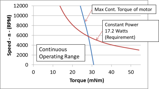
This leaves only two options to solve the problem: select a different motor with much higher torque or examine potential gear reductions. Details of gear reduction can be reviewed in the Gearing Systems section, but as our robot´s operating point is so far outside of the this motor’s continuous operating range, it is likely better to examine other motors first.
![]() Gear ratio rule of thumb: the least gear ratio the better due to weight reasons, backdrivability, efficiency. However, a high mismatch between the motor inertia and the load inertia can enter into resonance. This can be solved increasing the gear ratio.
Gear ratio rule of thumb: the least gear ratio the better due to weight reasons, backdrivability, efficiency. However, a high mismatch between the motor inertia and the load inertia can enter into resonance. This can be solved increasing the gear ratio.
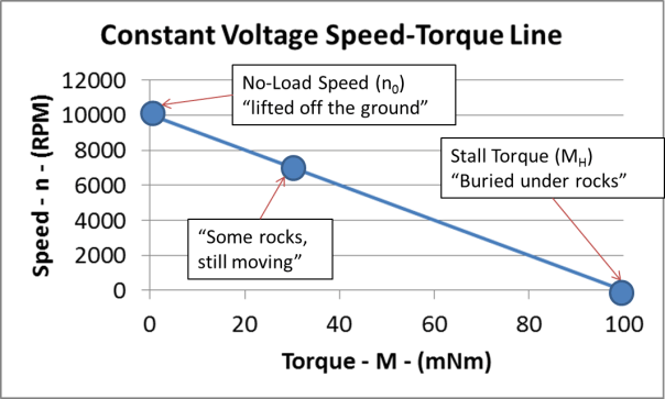
5. Stall Torque, No Load Speed and the Constant Voltage-Speed Torque Line
A constant voltage speed-torque line plots all of the speed and torque combinations possible with a constant voltage input. Imagine that the our robot has a single motor powering it with a constant voltage applied to the motor, and as it’s running, someone decides to continually place heavy rocks on top of it. As more rocks are placed on the robot, naturally it would slow down because of the higher torque needed to move the increasingly heavier robot. At some point, the total weight of the rocks would be too heavy, and the robot would no longer be able to move, i.e. the robot would be said to have “stalled out”.
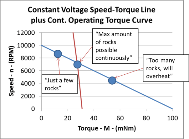
Now the maximum continuous torque curve can be plotted on the same graph as the continuous voltage speed-torque line, shown below in Figure 8. Assuming that the motor is only running at this voltage (or this is the maximum voltage that you system could apply to this motor) you can use next Figure to determine how many rocks the wheeled robot can carry before the motor will overheat.
To determine what the speed-torque line looks like for a different applied voltage, the equations below can be used. The new no-load speed (n0) is calculated using the new voltage (U) and the speed constant (kn) which is a property of the motor and can be found on the motor’s data sheet.


By plotting the maximum continuous torque requirement over the speed-torque lines for various voltages, it can be visually understood that to maintain constant torque, the voltage must increase as speed increases. Maintaining constant torque is also equivalent to maintaining constant acceleration, and having constant acceleration can be very desirable in many motor control algorithms.
Figure below also shows that if a constant torque of 20 mNm is required, there is a “dead-zone” from 0 to 7.2 V where the motor will not move and will be at a stall torque condition.

6. Gearing Systems
Before this section, the operating point was calculated to be 865 mNm torque and 189.86 rpm speed while the motor torque curve examples are operating at much lower torques (<100 mNm) and much higher speeds (>5000 rpm). This is an obvious disconnect, but one that can be solved by selecting a motor with higher torque or by using a gearing system.
Before determining that a gearing system is required, it is beneficial to look for motors that are closer to meeting your operating point without a gearing system. The addition of a gearing system will add weight and cost, and reduce efficiency.
In practice, the converted output power is always somewhat lower than the input due to gear efficiency losses (ηG).
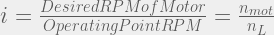
The first step in choosing a gearing system is to determine the desired gear ratio (i). The gear ratio is the ratio between what the motor is able to continuously spin on its own compared to the desired operating point speed. As described before, the operating point for our robot is 865 mNm and 189.86 rpm and the motor selected requires an operating speed above 6000 rpm and below 12000 rpm (motor limiting speed) to achieve 17.2 W continuously, as shown in Figure 6. Many times when looking up gearing information, the desired operating point is called the load. From this point on, the operating point of the robot will be considered the load. Likewise, the operating point rpm will be called the load speed (nL) and operating point torque will be called the load torque (ML). In order to differentiate between the desired speed and torque of the gearing system’s output shaft and the speed and torque the actual motor is running at, the speed and torque of the motor will be called motor speed (nmot) and motor torque (Mmot). Using those terms, the maximum and minimum gear ratios (i) can be calculated using equation below.


In this example, the gear system would require a gear reduction in the range of 31.6 to 63.2.
![]() Rarely is the exact gear ratio you want actually available, but a great rule of thumb is the lower the ratio required, the better the efficiency.
Rarely is the exact gear ratio you want actually available, but a great rule of thumb is the lower the ratio required, the better the efficiency.
If a gearbox is selected with a 35:1 ratio, the motor speed (nmot) is calculated with the equation below.

The equation to calculate the motor torque required is shown below for a gear system with 35:1 ratio and 80% efficiency.

The calculated motor torque and motor speed can then be used to calculate the motor power required to input to the gearbox.
![P_{mech} [W]=\frac{M_{mot} \cdot n_{mot}}{\frac {60} {2\pi}}=21.49 W](https://s0.wp.com/latex.php?latex=P_%7Bmech%7D+%5BW%5D%3D%5Cfrac%7BM_%7Bmot%7D+%5Ccdot+n_%7Bmot%7D%7D%7B%5Cfrac+%7B60%7D+%7B2%5Cpi%7D%7D%3D21.49+W+&bg=efefef&fg=555555&s=2&c=20201002)
This new power value will be compared against your current motor and it may be necessary to select a new motor.
If a gearing system is selected from the motor manufacturer, there will likely be data sheets available. The data sheet will list some basic information about ratios, speed limitations, torque limitations, and force limitations that you must double check, even if the above equations work out.
In some cases a custom designed gear ratio is required, thus a custom gear set as well. There are many great references for gear design. A couple good rules of thumb to keep in mind are:
- Make sure that your gears are always of the same modulus so that their teeth mesh properly.
- Never create a gearing system that has a single stage with a gearing ratio greater than 3:1 as it can cause your gears to lock up (i.e. you may need several stages of gearing in order to achieve the desired overall gear ratio).
6.1. Checking Inertia Mismatch
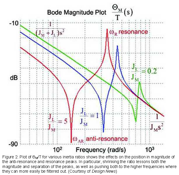
In a perfect system with an infinitely stiff motor shaft and coupling, the rotor would spin and turn the load along with it. In reality, all couplings have some degree of compliance. We can model the shaft/coupling as a spring with spring constant Ks. In such a case, when the shaft begins to turn and encounters a high JL, the shaft winds up and the load at best lags the rotor and at worst either moves the opposite direction from the rotor (anti-resonance) or wildly amplifies the force applied by the motor (resonance). The frequencies of these points essentially define the usable bandwidth of the motor across which the system can optimize motion to effectively deliver the load to the commanded position or move it at the commanded velocity.

Let’s take a closer look at how inertia ratio and coupling stiffness interact in our compliantly coupled system to introduce mechanical resonances that degrade motion. We start with the expression for angular acceleration for both the motor and the load.
Now let’s take a closer look at how anti-resonance and resonance spikes can potentially interfere with the tuning process and was system performance. Under normal circumstances, a servo would be tuned by analyzing the feedback and adjusting the drive signal to achieve more or less consistent response across the operating frequencies of interest. This process typically starts with increasing the gain to optimize system response. The problem is that in the curve shown in the next Figure, increasing the gain on the drive signal would push the resonance peak up past unity, causing erratic behavior like the bottle flinging.
The standard way to address this issue is to apply a low-pass filter that removes the two spikes (or any secondary resonances, for that matter). This works when the resonances fall at high frequencies, but when they fall at lower frequencies, that filtering technique sacrifices much of the usable bandwidth of the axis. It might be possible to raise the gain but the system might not be able to complete the motion cycle the allotted time.
To boost the frequency of the natural resonance, we can increase the spring constant or modify the inertia ratio by either increasing motor size or decreasing load inertia. Working with a more powerful motor typically adds to cost, size, weight, and energy consumption. Using the stiffest possible shaft for the coupling can improve the situation, but here, too, there are drawbacks. Ultra-stiff shafts require very accurate installation. Any alignment errors can cause premature wear on the bearings, leading to early failure.
Direct-drive motors provide another solution for the right application. Also known as frameless or kit motors, these designs involve making the motor a part of the load. One example would be a conveyor belt for which the rotor of the motor protects out as the axle for the belt. In such a case, KS rises toward infinity. These designs can tackle enormous inertia mismatches and still position effectively. On the downside, they are more complex to install and very unforgiving of misalignment. They may work well in robotic arms, for example, but in a factory environment that relies on maintenance staff handle replacing failed components, they may not be a good fit.
Reduction ratios and reflected inertia
Another way to address the issue of load inertia is to add a gearhead. We define the gear ratio N for two gears as the ratio of their diameters:
N = D2/D1
If we attach a motor producing torque 


Meanwhile, the gearhead scales the load inertia “seen” at the motor shaft as:
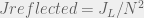
In other words, the addition of the gear reducer boosts the torque linearly but reduces the reflected inertia affecting resonance by 1/N2. “Reduction ratio is kind of the magic bullet,” says Bryan Knight, automation solutions team leader, Mitsubishi Electric (Vernon Hills, Illinois). “Sometimes going to a smaller motor and better gearing can give you a better inertia mismatch.” A standard 3:1 gearhead could reduce a potentially troublesome 54:1 inertia mismatch to 6:1, for example, while increasing torque by a factor of three at the load side.
7. Radial Load Calculation
The specification for the GP 26A gear system rates maximum radial load at 12 mm from the flange. It is important to review the details of how the manufacturer rates the maximum radial load. On the wheeled robot, the radial load is applied based on the location of the wheels. This differs from the rating, so the equivalence must be calculated.
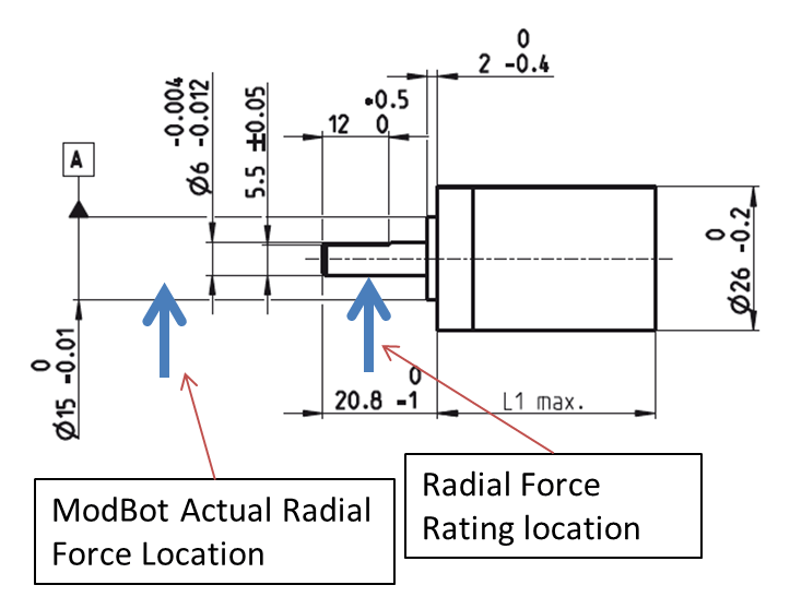
Using cantilevered beam equations, the equivalent force at 12 mm is calculated, as shown here:
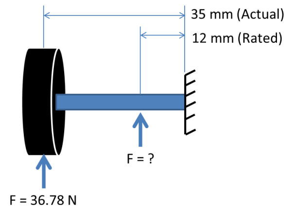
The calculated force during operation, 107.3 N, is below the maximum rated, 140 N. However, the resulting safety factor of 1.3 is not very large, especially when this is just a simple static calculation and does not consider peak driving loads or weight imbalance. It may be worthwhile to revisit the design and move the wheel closer to the gearbox flange to improve the safety factor.
8. Converting from Mechanical to Electrical Requirements
The constant voltage speed-torque line was the first relationship investigated between mechanical and electrical requirements. However, more requirements must be investigated to gain a broader understanding of the interface with the power system and battery. The mechanical requirement of the motor has been defined, now the electrical energy can be calculated.
Electrical power (Pel) and mechanical power (Pmech) have the same units but in converting between the two, there will be an efficiency (η) loss.
![P_{mech} [W]=P_{elec} \cdot= \eta](https://s0.wp.com/latex.php?latex=P_%7Bmech%7D+%5BW%5D%3DP_%7Belec%7D+%5Ccdot%3D+%5Ceta&bg=efefef&fg=555555&s=2&c=20201002)
This efficiency loss can be considered the system efficiency loss. It will include how effectively the electrical energy is turned into mechanical energy as well as the mechanical efficiency of driving a gear system. For example, if the system has a total efficiency of 50%, the electrical power required will be twice the mechanical power.
![P_{elec} [W]=\frac {P_{mech}}{0.5} =42.89 W \eta](https://s0.wp.com/latex.php?latex=P_%7Belec%7D+%5BW%5D%3D%5Cfrac+%7BP_%7Bmech%7D%7D%7B0.5%7D+%3D42.89+W+%5Ceta&bg=efefef&fg=555555&s=2&c=20201002)
9. Determining Voltage and Current Requirements from Power Requirements
Once the electrical power needed is calculated, it is used to determine the specific voltage and current requirements. Similar to mechanical power being comprised of two parts, speed and torque, electrical power is also comprised of two parts, the voltage (U) and the current (I). Voltage and current have similar trade-offs to speed and torque, as shown in the Equation below:
![P_{elec} [W]=U \cdot I](https://s0.wp.com/latex.php?latex=P_%7Belec%7D+%5BW%5D%3DU+%5Ccdot+I&bg=efefef&fg=555555&s=2&c=20201002)
In general, there is also a direct relationship between speed and voltage, and also between torque and current. For a voltage controlled DC motor, the higher the input voltage, the higher the speed and likewise, the higher the torque required, the higher the current draw. Therefore, it is important to calculate the voltage and current requirements at:
- the maximum speed that you will be operating at, which is commonly one of your operating point(s) and/or the maximum continuous operation voltage rating of the motor you’re considering
- the conditions that you will be operating at most often, also commonly your operating point(s)
- the maximum torque you will be operating at (which is commonly the stall torque of the motor you’re considering, which can occur when you are starting up or switching directions)
In any of these cases, two of the three values in Equation 16 above are known, and the remaining value can be solved for.
For the maximum speed case, recall the discussion of constant voltage speed-torque lines. If the operating point for a motor does not fall on the motor’s rated voltage speed-torque line, the voltage input to the motor will be lower than the motor’s rating. That means for the same power the current will also be higher. In our case case, 24 V corresponded to the robot´s maximum speed, so plugging this voltage and the power into the equation:
![25 [W]=24 Volts\cdot I](https://s0.wp.com/latex.php?latex=25+%5BW%5D%3D24+Volts%5Ccdot+I&bg=efefef&fg=555555&s=2&c=20201002)

Low current requirements are often not an issue for power system development but it is good to have them calculated.
For the final case using maximum torque, the calculation can be treated in a similar manner as the maximum speed, i.e. by examining the torque-speed curve.
In many situations the motor is operated at its maximum continuous voltage rating, and in these situations, the maximum torque is almost always the motor’s stall torque. This value is typically on the motor’s data sheet along with motor’s associated current draw, which is commonly called the motor’s stall current or starting current (IA). Operating at the stall torque and the maximum continuous voltage rating effectively turns the motor into an electric stove. All of the electric energy input goes to Joule power losses because no mechanical work is being done. By recalculating the winding temperature rise with 100% of the energy going into PJ, it is easy to see that the motor will not be able to operate at this condition for long.
9.1. Re-evaluating Motor Selection Based on Voltage and Current Requirements
As the maximum current is a very important characteristic in power system design, it may be necessary to examine other motor options if your motor’s maximum current is deemed too high by your power system.
9.2 Thermal Behavior of Motors
The inefficiency of the electric motor, as discussed in the previous sections, has another important effect on motor operation that should be addressed as part of your selection process. Power losses due to inefficiency are typically converted into heat. If the thermal energy is not dissipated, the motor will begin to overheat and if allowed to reach a certain temperature, it can sustain permanent damage. This section describes how to perform some motor temperature safety check calculations to see if cooling methods need to be explored further.
The power loss and the resulting heat can be calculated starting with the efficiency at a given operating point. Although there are different kinds of power loss in a motor, i.e. thermal and frictional power losses, all of the motor’s power loss is typically combined into one value called the motor’s efficiency losses or the Joule power losses (PJ).

The power losses (PJ) are responsible for increasing the temperature in the motor, therefore this amount of heat must be dissipated, which can be solved for by rearranging the equation above and plugging in the values determined in the previous sections.

Within the motor there are two primary thermal resistances that are considered; these are listed in the motor’s data sheet. The first, Rth1, is between the rotor and the stator, (the part of the motor that surrounds the rotor) and the second, Rth2, is between the external surface and the environment. Combining the thermal resistance with the thermal power, the temperature delta (ΔTW) of the motor can be calculated between the motor winding temperature (TW) and ambient temperature (TU) as shown in the equations below, with the values of the Robot´s motors inserted. Rth1 and Rth2 can both be found on the motor’s data sheet.

Alternately, in some cases the power losses due to inefficiency may not be expressly known because the motor is operating at a different point or the efficiency of the gear system is difficult to calculate. However, using the motor winding resistance (R) and current (I), the thermal energy can be calculated and these values can be measured easily when the robot is operating. Using the winding resistance, R25, from the data sheet of RE 30 (PN 310009) the following calculation can be done:

The two calculations obviously show some differences. Some of that can be accounted for with the change in resistance of the windings due to temperature. As the motor gets hotter, the resistance increases. The actual winding resistance at an elevated temperature (RT) can be calculated at an elevated temperature via the equation below where the ambient temperature is considered to be 25oC. The thermal resistance coefficient of copper is 0.0039 (aCo). By using the calculated winding temperature increase (ΔTW) from above, it can be combined with the ambient temperature to give a 49.9oC estimated winding temperature.

As a check, the actual winding resistance (RT) at a higher temperature can be put back into Equation to calculate the temperature rise.
The values calculated by the two methods still vary slightly and the process can be re-iterated until a small enough difference results; however, the values shown here are close enough for an estimate of the winding temperature rise, so the iterations can stop here just after one round. The important constraint to check is that neither method of calculation yields a temperature rise that will cause the motor to operate outside its maximum winding temperature (Tmax). In this case, assuming a 25oC ambient temperature and using the maximum calculated temperature increase of 29.3oC, this will result in an operating temperature of 54.3oC, which is well below the 125oC Tmax of this motor. If your motor’s operating temperature was above your motor’s Tmax, you could either consider a different motor or begin to investigating cooling options. Cooling can be as simple as adding a fan to blow air on the motor or in some cases, better motor mountings can be designed or better housings can be available from the manufacturer. For example, if the mounting or housing of the motors allows better heat transfer, then Rth2 can be reduced by a significant amount. If the mounting of the motor has metal flanges, the Rth2 value could decrease by 80%. Some motor manufacturers will show the increased torque capability if the Rth2 value is decreased. . In Figure below, the standard torque rating is shown as well as the torque rating with Rth2 decreased by 50%.
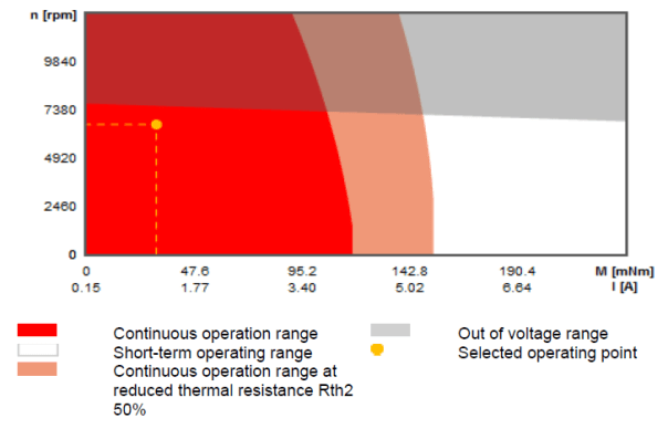
Remember, the maximum continuous operating torque line is determined by thermal limits. If the motor receives better cooling, the maximum continuous operating torque line can increase. As beneficial as this sounds, it is also equally important to remember that if the motor has reduced cooling or is operating at a higher ambient temperature, the maximum continuous operating torque line decreases. The amount it decreases is not always straightforward to calculate so the key takeaway is that if the motor temperature is anticipated to be too high, cooling should be investigated and tested before full implementation.
10.Common Additional Considerations when Selecting a Part: Motor Selection Example
Whenever you have to select a part for your system, there can be lot of additional factors to consider other than just the equations. The sections just prior to this one went through the technical procedures of helping you find your best motor based upon the initial operational requirements. This is often the most challenging aspect of picking a motor (or any part in general) but this section provides a few questions you should ask yourself that may help you improve the selection of a part or change how that part is installed. These questions tend to focus on motor selection, but they provide a good example of how you should question any part’s selection. As always, it is best to consider all of the ways your system will be used, including all of the extreme or undesired conditions it may encounter.
- Part Availability
- Cost – Every project has some limits on its budgets, and many times you have to ask, is the improved performance worth the cost? Would choosing a lesser motor that still meets all of your core requirements be acceptable if it means being able to purchase an extra motor that will better improve your overall system performance?
- Supply and Delivery Time – Can you find a supplier that has the number of motors you need in stock? What is the lead time to get the motor(s) to you? Does that give you enough time to test the motor(s) after you finally receive them? What if the tests go poorly; do you have time to get and test a replacement motor or other modifications to your system?
- Environment
- Ambient Temperature – Will the motor have ambient air surrounding it? Will it need to maintain performance at high ambient temperatures? What protections are in place for high temperatures?
- Water – Any possibility the motor could see a splash or submerged condition? Will it need to be cleaned using liquids?
- Dirt – What amount of dirt and dust will the motor be exposed to? Will this require any effort to protect the motor?
- Corrosion – Will the motor encounter any corrosive chemicals? How does the manufacturer rate corrosion resistance? (Maxon bases it on the standard: DIN EN 60068-2-30)
- Serviceability
- Time – Are there time constraints on how fast the motor can be changed? What happens in event of a motor failure during operation or during the competition? How many steps are required to access the motor? How many different tools are required to access the motor?
- System or Sub-system Replacement – In the event of a failure, what needs to be replaced? Can the whole motor, gear, sensor combination be replaced or does each individual part require replacement?
- Installation – Many parts get swapped in and out during testing; are there any precautions required for installation and removal to prevent damage? Where are the motors kept when not installed in your system? Is it possible to install the motor with the incorrect orientation?
- Backups – How many motors will be available in the event of a failure? How long does it take to get a new one? Do you have the budget for spare parts if the lead-time is long?
- Changeover – Will the system require any of the interfaces to have quick changeover? Have all of the steps been reviewed? Will the quick changeover impose any risk for damage or incorrect assembly? Have the operating conditions been reviewed for the new system configuration? (e.g. ModBot must change to DuneBot)
- Packaging
- Physical size – Will the motor, gear system, and sensor physically fit into your system? What is better, a long and skinny motor or short and fat one? (CAD models are often available from the manufacturer.)
- Clearances – What clearances are required due to tolerances of all other parts of your system to ensure no interference? Will the motion of the motors reduce the clearances, even as a result of flexing or vibration?
- Wires – Wires must go somewhere! A common mistake is to neglect the wires in mechanical design. What has been done to account for the package space? Are the wires properly supported such that there is no stress on the wires in order to prevent damage from tight bends or fatigue? How many wires will be required? What length of wire is required? Encoders increase the wire count significantly, are they accounted for?
- Cooling – How is the packaging changing the cooling capacity of the motor? Will other hot components be nearby? Is liquid cooling necessary? Is liquid cooling an option? What about fans? Is Rth2 anticipated to be better or worse than what the motor was rated? Will the heat from the motor damage nearby components, such as paint or wires?
- Weight – How much weight was planned for the motors? Is this good or bad for the overall system weight? Does the location of the mass of the motor change any of the vehicle dynamic calculations, such as inertia or center of gravity?
It is clear that a single motor will not be the best in every area and compromises will need to be made. For example, the motor with the highest torque will not be the motor with the smallest diameter.


[…] Electric motors: it is important to distinguish the types and to know the basics of operation of the most used motors, e.g. DC brushed, DC brushless, PMSM, steppers, servos, etc. In a typical project, very frequently, one has to select the proper motor for an application and possibly the combination of motor and gearbox. I have published a very useful guide to select an electric motor for a simple robotic application. (https://enriquedelsol.com/2017/11/19/motor-selection-for-robots-i/). […]
LikeLike
Why are you only including 0.865mNM torque what about torque required overcome weight?
LikeLike