The inverter of the PWM drives does not produce sinusoidal output voltage waveforms; instead, it generates a continuous train of pulses which are transmitted to the motor terminals via the motor cable. Peak pulse voltage atthe drive outputis equalto the drive DC bus magnitude (Vbus) and it is characterised by the step rise and fall times (trise, tfall) controlled by the GTO, BJT or IGBT semiconductor switching device used.
The peak pulse seen at the motor end is not necessarily the Vbus sent by the drive and it depends on a combination of factors which define the whole system behaviour. These factors are: the trise and tfall characteristics of the PWM, the cable transmission line characteristics, the cable length and the motor impedance. A commonly used model suggests that peak voltages up to twice of the Vbus can appear at the motor end of the cable, although in other references, more than double of that voltage is observed in real experiments.
The process leading to this can be summarised as follows:
At the beginning of each PWM pulse, the drive has to charge the characteristic inductance and capacitance of the cable.
When the edge reaches the motor end of the cable a reflection occurs because of the step change in impedance (the one of the motor is almost invariably much higher thanthe one ofthe cable). This effect is more pronounced with small motors due to their higher impedance.
The reflection then returns to the drive, where it is reflected again but in negative sense, and when it returns to the motor, it cancels the overvoltage.
The overshoot lasts about twice the time of flight in the cable. If the rise time of the pulse is longer than twice the time of flight in the cable, the overshoot is cancelled before it reaches 100%.
A measure of the overshoot size that can be caused on the motor end of a cable is defined has a “Reflection Coefficient”, and it is a function of the cable surge impedance (Z0) and the load surge impedance (Zload) presented at the receiving end of the cable.
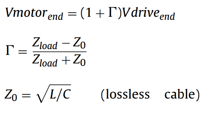
where L is the cable inductance per unit length of cable and C is the cable capacitance per unit length of cable. Whenever the cable surge impedance does not match the surge impedance ofthe motor, a reflected wave will occur at the motor terminals.
There is a common agreement in the literature about the adverse effects in motor control when using long cables due to the over-shoot voltages. A research has used a different set of simulated with a PMSM (Permanent Magnet Synchronous Motors) motor in Matlab©. They implement a PI regulator and study the influences on the control performance during velocity control. The results show that the speed controller rejects load disturbance faster at shorter cable lengths. On a different test, by loading the motor at a certain instant with a constant torque, they show that steady state error is increased when the speed is lowered.


Leave a comment