The trend towards wide scale use of Brushless Motors is being driven by manufacturing
cost reductions, improved efficiencies, greater reliability, availability of improved drive
electronics, and the availability of improved sensors for motor control.
The brushless motors, independently whether they are PMSM or BLDC motors, require to know the relative position of the windings with respect the motor poles. To do this, a set of Hall Effect sensors are typically employed and placed between windings. An alternative option is to use the positional feedback from more accurate sensors to determine the presence of the magnetic field without using Hall Effect sensors. However, an intelligent drive is required to perform this count and issue the signal that conmutates the phases. This action is performed automatically with the bipolar Hall-Effect sensors.

Hall Effect sensor
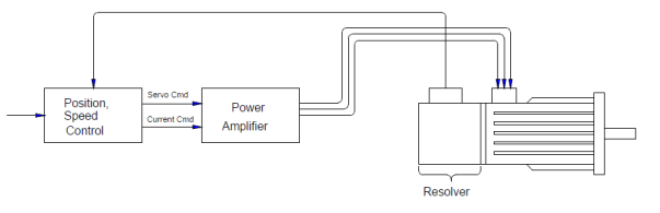
For the majority of applications in the US and Japan, the trend in brushless motor sensor designs is moving away from Hall boards and feedback elements to integrated devices. For resolver applications, it can be handled by adding a dedicated set of 2, 3, or 4 speed windings for commutation, or it can be handled with a single speed winding and an intelligent drive.
The elimination of the Hall sensors from the BLDC motor eliminates many of the potential problems which can occur in a motor application. Hall devices are sensitive to acoustic noise, current spikes, temperature, EM fields, and can be difficult to align, which results in torque ripple. When a BLDC motor is used in a servo application with a high resolution feedback sensor, Hall sensors are redundant and consume space. They also add to motor length, assembly costs, cable harnessing complexity, and decrease overall reliability. The use of an encoder or resolver to eliminate Hall sensors in this situation is not only cost effective, but also improves the overall system performance.
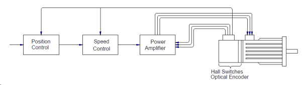
Drive with Hall board, Encoder or Resolver for Commutation and Feedback a caption
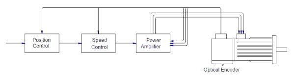
Drive with Commutating Encoder
Encoder Types.
When an encoder is used as the feedback element, there are a variety of types to choose from. The following is a short summary of the predominant types currently available.
1. Incremental, (TTL)
Readily available from a wide variety of Suppliers. Almost unlimited line count availability up to 5000 cycles per revolution. Special line counts and output options
are easily obtained.
2. Incremental with Commutation, (TTL)
Becoming more common in the US and Japan, availability is somewhat constrained by lack of industry standards. Mounting configuration, signal conditioning, and power supplies vary widely. Available in line counts up to 8000 for 2, 4, 6, and 8 pole motors. They are being developed in both hollow-shaft and modular versions by a variety of encoder suppliers.
3. Incremental with Commutation, (Sine wave)
More common in Europe, this type of encoder generally has sinusoidal quadrature
outputs, with a 1 volt pk-pk amplitude. Commutation is accomplished using a quadrature one cycle per revolution output.
4. Absolute Single Turn, (TTL/Parallel)
Less common for drive applications, these are usually found in 10 to 12 bit versions. Larger word sizes are available, but costs become a real issue and make them unsuitable for all but the most specialized applications.
5. Absolute Multi-turn, (Sine wave Incremental, Serial Absolute)
These encoders are generally based upon a 12 or 13 bit single turn absolute encoder, with a 12 bit turn counter yielding 24 or 25 bits of position information. Although these have been available for some time, they have been too costly for widespread applications. Recent developments in Europe, however, are making these more available, and costs are starting to come down. These encoders contain an incremental output with A, B, and Reference pulse, a serial absolute interface, and commutation outputs. Commutation output is derived from the MSB of the single-turn absolute. The Incremental tracks are derived from the LSB of the absolute encoder, and generally result in a 2048 or 4096 cycles per revolution incremental signal that is suitable for use in high-speed servo controls.


Leave a comment